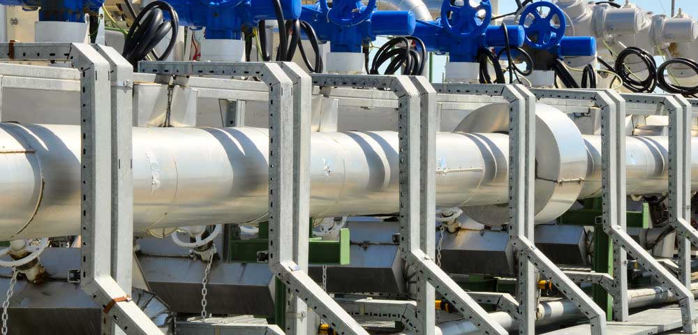
Manifolds are used extensively throughout the oil and gas industry for the distribution of gases and fluids. They are designed to converge multiple junctions into a single channel or diverge a single channel into multiple junctions. Simple manifold systems typically are used to divide one supply input to multiple outputs, while more complex systems incorporate integral valves or an electronic network interface. The specific features of a manifold will largely be determined by the specific application it is to be used in.
In the oil and gas sector, manifold systems are used within exploration, development and production phases, particularly in wells using surface testing equipment. They can perform any number of functions, including:
- Divert oil or gas to surge or gauge tanks for storage or measurement
- Direct flow to a production line, or from the separator to crude oil burner for disposal
- Maintain flow when testing requires that certain equipment be pulled out of service.
Choke manifolds combine high-pressure valves with multiple chokes and are used to lower pressure at the well head, which is vital to gas flaring. Multiple chokes are required so that if one fails the flow can be directed through another. Chokes may be adjustable or fixed; however, most systems have a combination of both.
Choosing the Right Manifold
When choosing a manifold system, there are a number of considerations to take into account. Some of these include:
Pressure – Pressure is exerted by the oil or gas as it flows through the system. Most compressed gases, for example, are unlikely to surpass 3,000 psig; however there are situations that can raise gas pressures to as much as 6,000 psig. It is essential that the weakest part of the manifold system can handle pressures greater than the force exerted. In addition, regular maintenance is required to ensure that wear and cyclic fatigue has not compromised the manifold’s ability to handle its designed maximum pressure.
Flow – The size of the pipes, valves and other components of the manifold system determine the maximum flow rate. Careful consideration should be applied when predicting future flow requirements for your application. For liquids, such as crude oil, flow rate is measured in gallons per minute, while gases are generally calculated in standard cubic feet per minute.
Temperature – Temperature range of manifold equipment should be based on careful assessment of both current and future uses and applications. For instance, a manifold may be designed to handle liquids or gases of a specific temperature; however, as production progresses, the PVT (pressure, volume, temperature) characteristics of the raw product may change. Ensuring that manifolds are designed to handle such changes is important to preventing mechanical damage and preserving overall safety.
Manifold Material Selection
Manifolds can be made from a number of materials. Choosing the right material will ultimately be dictated by the operation the manifold will be used in.
For instance, the lightweight and corrosion resistant nature of aluminum suits applications dealing highly corrosive fluids and excessive wear. Steel, on the other hand, offers high physical strength and can be coated for greater corrosion resistance. Stainless steel is ideal for extremely corrosive applications. Ductile iron is used when both corrosion resistance and machinability are important. Thermoplastic or thermosetting polymers, of differing molecular weight and grade, can be used to provide protection against specific types corrosion and chemical attack.
Port and Valve Selection
The number and type of ports is an important design feature that will also change according to the manifold’s application. Port diameter is based on standardized national pipe thread (NPT) sizes. The number of inputs required determines the number of supply ports, while the number of outputs determines the number of outlet ports.
Complex manifolds often incorporate integral valves. In contrast to systems that attach valves to a to a base or subplate, integral valves must be assembled within the manifold. Integral valves may be solenoid, in which an electrical signal controls the valve via a pneumatic signal; or manually controlled by an operator.
Certain applications may require that manifolds incorporate additional features. Filters and traps, for example, remove contaminants within oil or gas in preparation for certain instruments. Adjustable chamber isolation, allows supply chambers to adapt to the state of process cycles. Electrical feedback signals indicate valve state and allows automated system response, while visual indicators are used when the valve status needs to be readily available.
The Bottom Line
In oil and gas, as well as other industrial sectors, manifold systems are essential components for the distribution of liquids and gases. They are vital junctions and safeguards in a wide range of processes. Choosing high quality manifolds, expertly designed and fabricated for your specific needs, is key to ensuring smooth and continuous operation of your facility.
